Here we are, in this third article, talking about an extremely important topic regarding the 3D configurator: lighting and setting up the environment (lighting and environment setup).
The user who uses the configurator must be able to manage the model by having a clear and defined representation of the environment in which he interacts: practically he will be captured by the navigation provided he has a well-lit object and with satisfactory materials.
In theory there are multiple lighting schemes but there are no hard and fast rules to adopt: everything is based on general principles and on the experience of what you want to be appreciated and highlighted.
Classic lighting schemes include:
1 point light scheme: used in situations where high contrast is required to express the dramatic mood of the scene;
2 point light scheme: this scheme, on the other hand, uses a primary light (key light) that illuminates the subject and adds a secondary light (fill light), with much lower intensity and with the aim of illuminating the shaded parts as if they were hit by indirect ambient light;
3 point light scheme: resumes the previous scheme, but with the addition of a third point light scheme that illuminates the edges of the subject separating it from the background (in jargon this light is called rim light).
These schemes adapt very well to the case of subjects to be illuminated in a studio where the presence of artificial light sources is required which must be properly managed.


In the case of a configurator, the point is to give emphasis to the object itself, without neglecting any part of it.
This translates into avoiding the introduction of shadow areas that could hide details and avoiding areas that are too overexposed, which would also lead to loss of detail.
In the case of our trolley, we have tried to adopt a 2-point light scheme with the integration of a 360 ° map to give importance to the specular reflections of the elements (e.g. plastic and metal).
In technical jargon this environmental map is called Cubemap and represents a 360 ° environment that the trolley reflects. It can be created from an equirectangular map that is broken down into 6 images, each to be mapped into a face of the cube that surrounds the scene.
In typically non-realtime representations this map is directly managed as an equirectangular map and usually in HDR (high dynamic range) format. On the other hand, in applications where performance and responsiveness in the controls plays an important role, an 8-bit per channel image can still be preferred, but still at high resolution.
Below is a general representation scheme of the 3D setting of our scene:
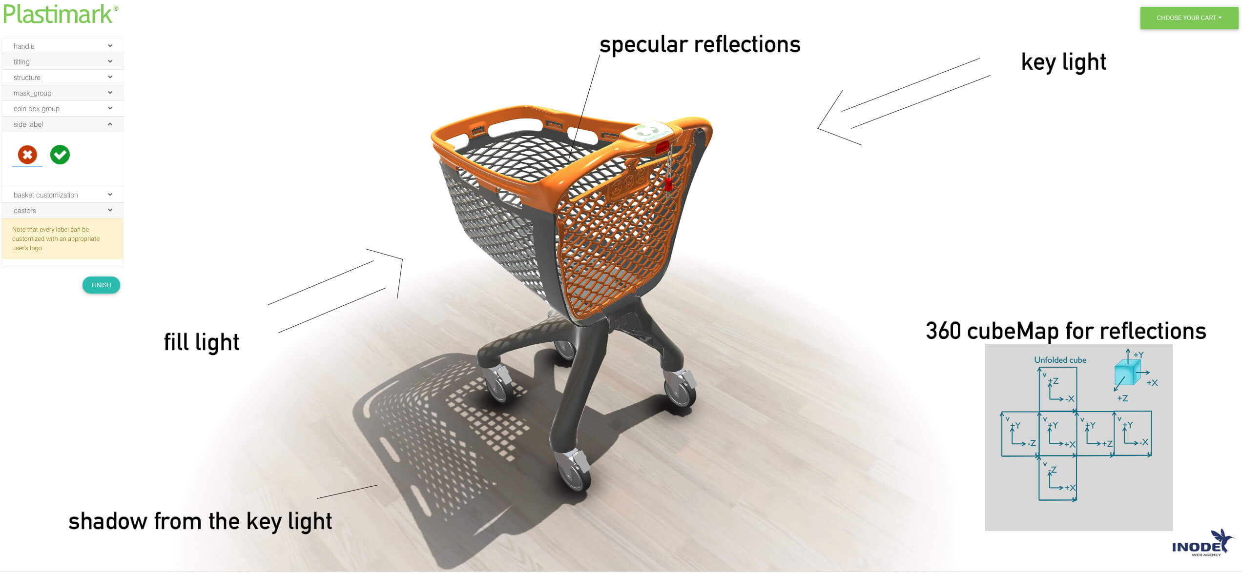
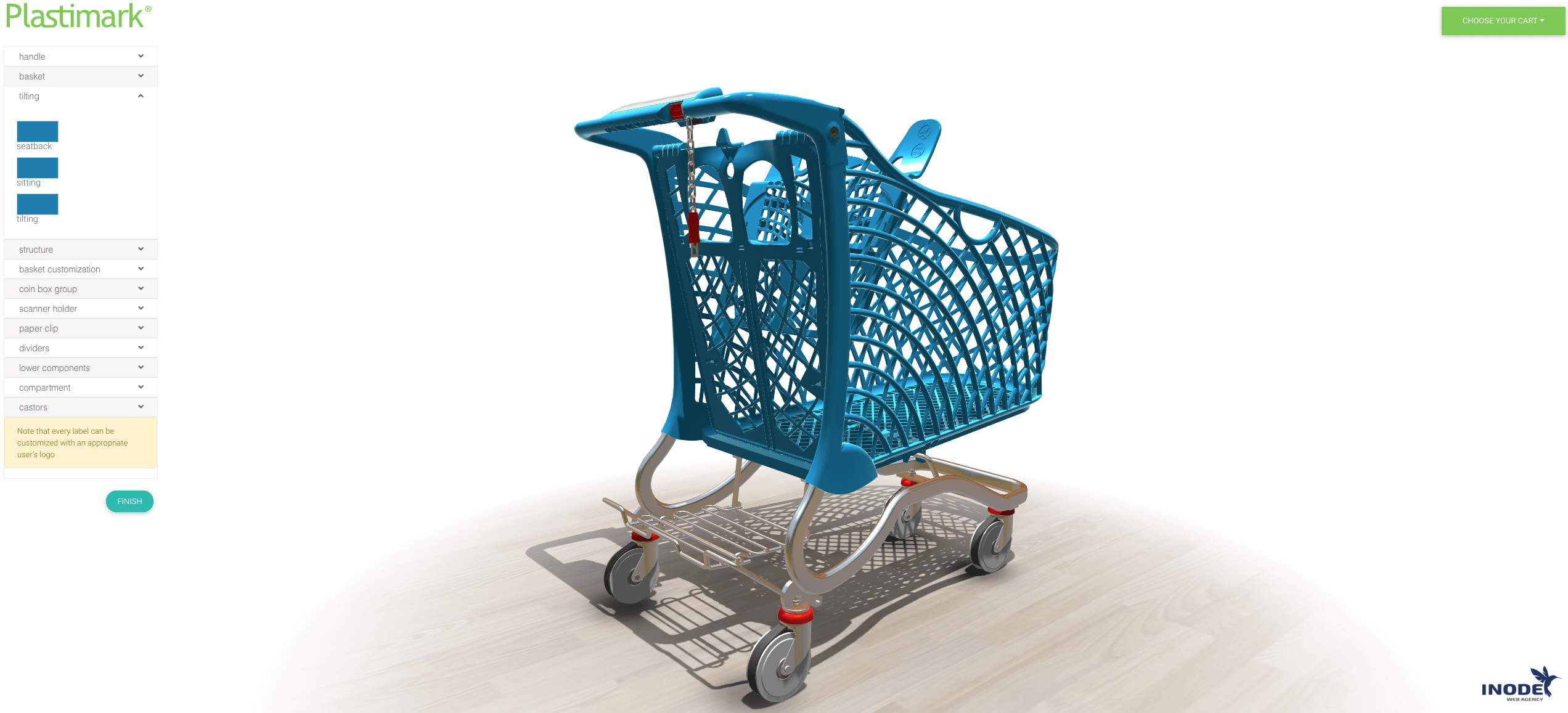
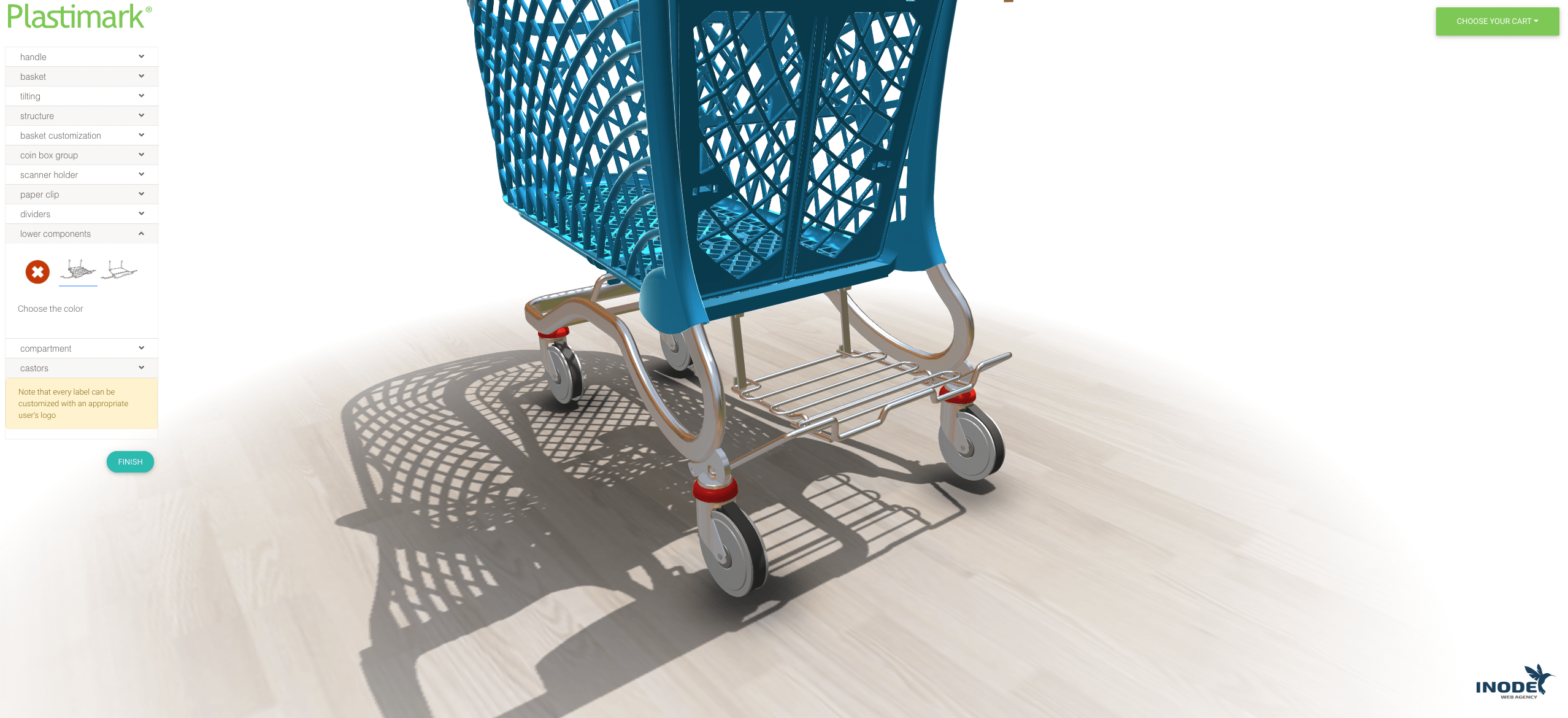
You can see how this setting of lights highlights the configurator, avoiding having areas that are too shaded or overexposed.
All this guarantees navigation around the object to observe its different details.
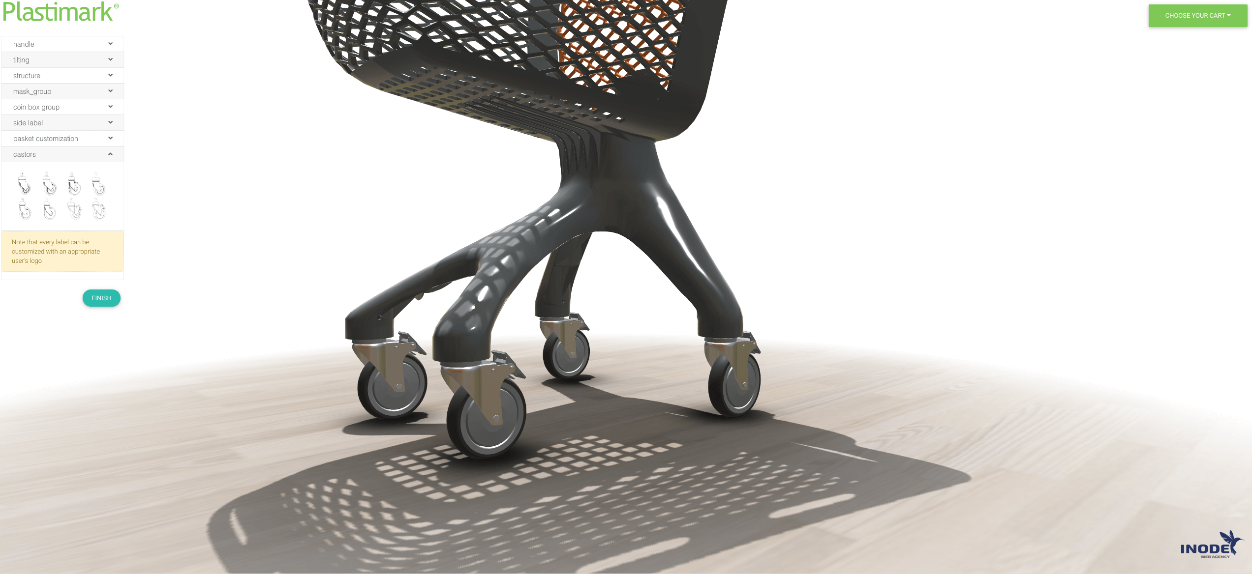
As regards areas such as wheels, for example, the reflections related to cubemap come into play.
If a 360-degree map were not present, most of the metal elements which, by their nature being conductors, diffuse very little and reflect a lot, the yield of the metal would appear mostly black with any specular reflections related to the key light.
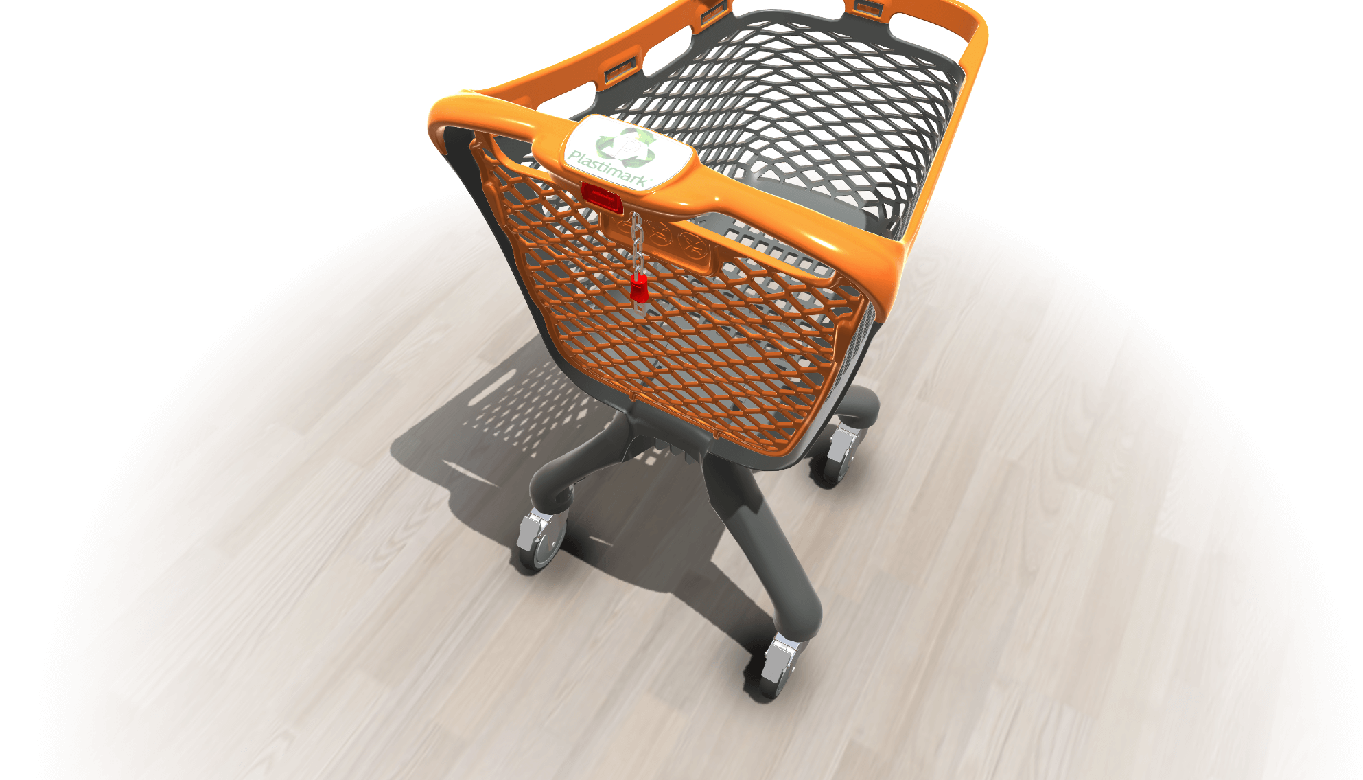
In this way we guarantee environmental reflections and a more natural result.
The surfaces of the model, if viewed flush, present the classic Fresnel reflection more pronounced as it happens in a real physical model.
In the next article we will talk about the parts of code used to make the configurator.
Stay tuned!